Schematic Diagrams
Presentations | English
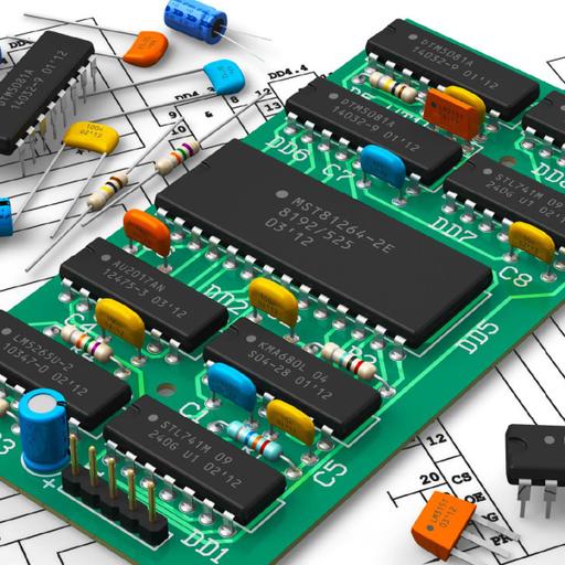
Schematic diagrams describe the main and auxiliary circuits for control, signalling, monitoring and protection systems. They are drawn in sufficient detail to explain to the user the circuitry and its mode of operation. They allow circuits to be ‘followed through’ when tracing faults. With the increasing complexity of electronic circuitry, discrete functional blocks, such as relays, are often represented as ‘black boxes’ on the overall schematic diagrams with only the input and output terminals to these units clearly identified. The characteristics of the ‘black boxes’ are identified by standard symbols and further reference to the complex circuitry inside the ‘black boxes’ may be obtained from separate manufacturers’ drawings. Circuit arrangements are usually shown on schematic diagrams according to their functional aspects. They seldom follow the actual physical layouts of the different component parts.

11.00
Lumens
PPTX (22 Slides)
Schematic Diagrams
Presentations | English
